

Oscillating water column (OWC) wave energy converters (WEC) are the most extensively studied and possibly the most reliable of all WEC devices.
The OWC is an artificial blowhole consisting of a chamber that is open beneath the waterline. The action of the waves moves the water column and, alternately, compresses and decompresses the entrapped air resulting in a bi-directional flow through an air turbine, which generates electricity. Due to the oscillatory flow characteristics, bi-directional (or self-rectifying) air turbines are generally adopted.
A fundamental step in turbine development is to conduct model-scale performance tests, however facilities that accurately simulate bi-directional, or oscillatory, air flows are relatively rare.
In 2018, AMC commissioned a bespoke test facility to generate high volume oscillating air flow. The main parameters of the AMC oscillating air flow test rig are:
- Chamber length: 3 m
- Chamber internal diameter: 1.5 m
- Ball screw driven by a 32 kW Servo motor
- 3 x linear bearings
- Piston working travel (maximum): 2 m
- Piston velocity (maximum): 1.25 m/s
- Constant velocity profiles
- Sinusoidal profiles
- Programmable profiles based using position way points and velocity
A system controller monitors the active piston position and velocity. Other measurements acquired with the dedicated data logging system include pressure and temperature sensors.
The air flow exit can be adapted to suit specific applications. Examples include: (1) a flange can be fitted to investigate the performance of flap/check valves; or (2) air turbine performance can be assessed by mounting an adaptor to the exit flange or via a bypass pipe. Orifice plates or venturi can measure bypass flow.
Key words: Wave energy; Oscillating water column; Turbine test-rig; Bidirectional air flow; Reciprocating air flow; Oscillating air flow; Self-rectifying air turbines; Experimental testing.
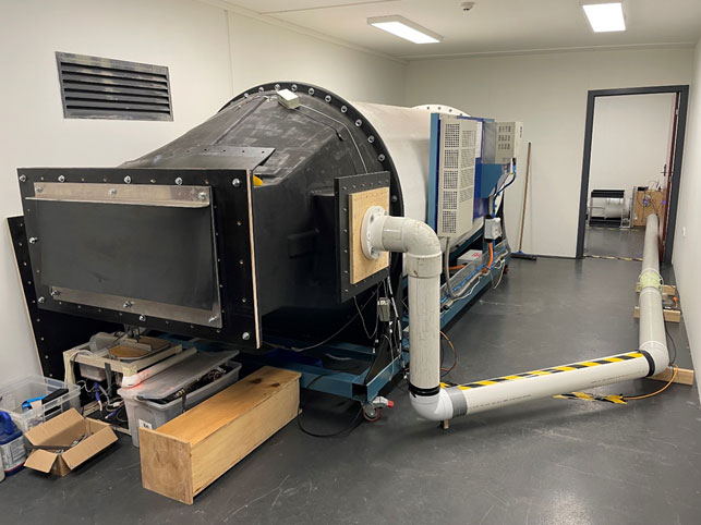
Figure 1: Photograph of the oscillating air flow test rig. The exit flange for mounting test samples, such as the flap valve shown, can be seen in the foreground. An air bypass pipe can be seen extending into a separate room where controlled tests on turbines can be performed.
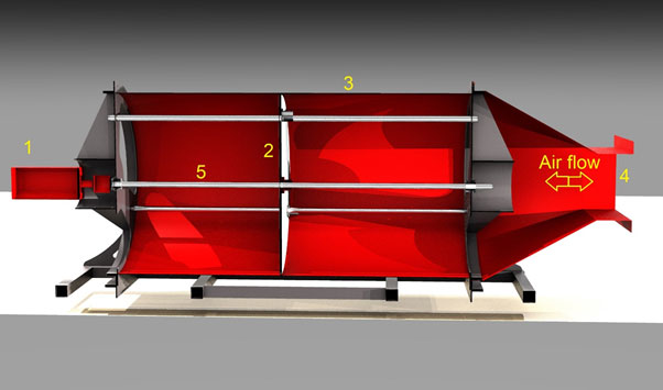
Figure 2: A cut-away diagram of the oscillating air flow test rig. Items include: (1) servo motor, (2) piston, (3) chamber, (4) exit flange for mounting test samples, (5) ball screw.
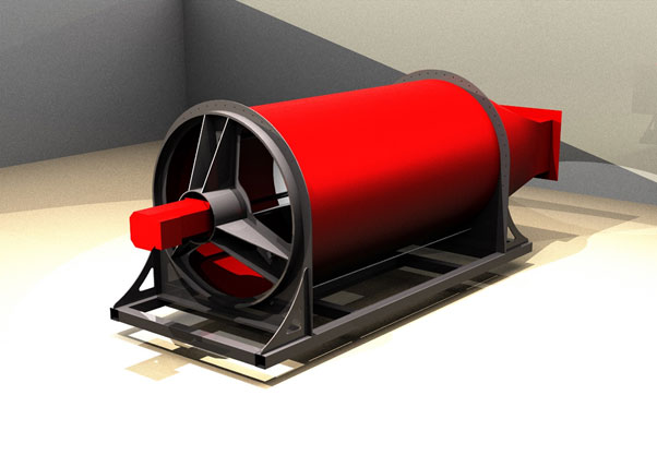
Figure 3: A diagram of the oscillating air flow test rig from the motor end. The chamber length is 3 metres and diameter 1.5 metres.
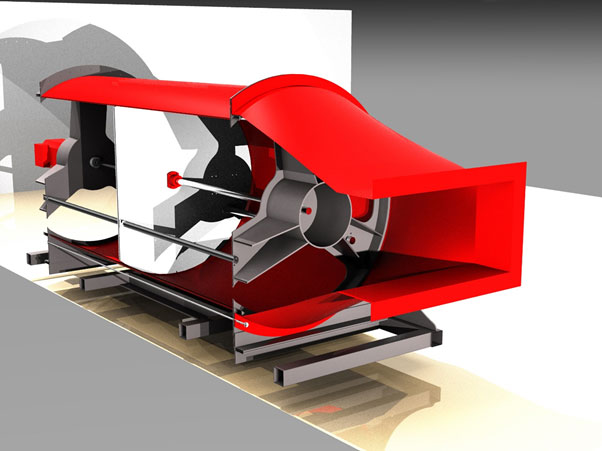
Figure 4: A cut-away diagram of the oscillating air flow test rig from the exit/test sample end.
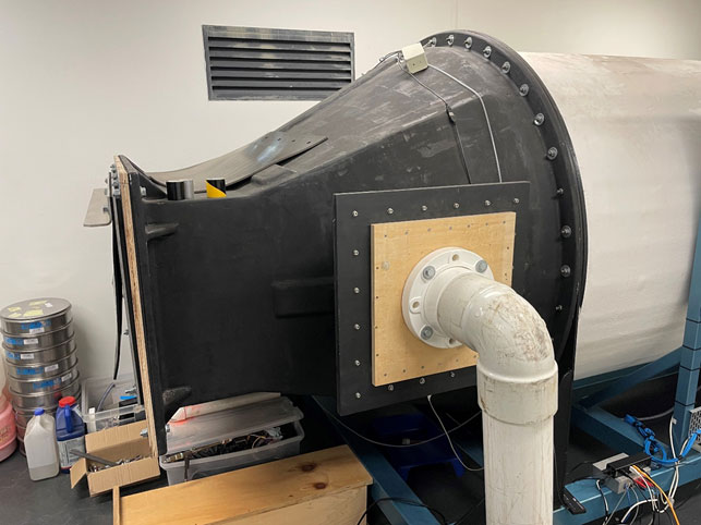
Figure 5: A photograph of the two exit flanges on the oscillating air flow test rig.
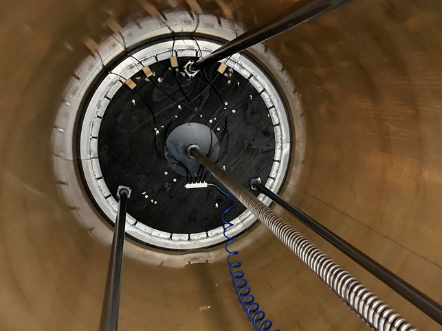
Figure 6: A photograph showing inside the chamber of the oscillating air flow test rig, including the ball screw that drives the piston. A small pool of silicone lubricating oil can be seen near the base of the piston.
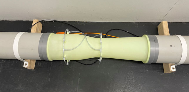
Figure 7: A photograph of the venturi in the air bypass pipe.
We gratefully acknowledge the valuable contribution from our research collaborator, Wave Swell Energy, in the development of this test rig.
